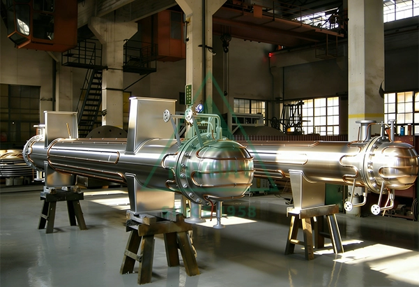
The installation quality of shell-and-tube heat exchangers directly determines their service life and operational safety. Improper installation details may lead to leakage, vibration, thermal stress cracking and other failures shortly after commissioning. Mastering key installation specifications is essential to ensure longterm and stable equipment operation.
Before installation, foundation acceptance is the first critical step. It is necessary to verify that the foundation elevation, levelness and reserved hole positions comply with drawing requirements. Installation can only proceed after the foundation strength meets design standards; otherwise, foundation settlement may cause equipment deformation. Equipment inspection must not be overlooked. Check whether the model, specifications and materials are consistent with design documents, and inspect the tube bundle, tube sheet and shell for transportation damage. Review or reperform pressure test records to confirm factory tightness and sealing performance.
Extra caution is required during lifting and positioning. Shell-and-tube heat exchangers are usually heavy, ranging from several tons to hundreds of tons. Only dedicated lifting lugs shall be used. Direct binding on the shell or tube bundle is strictly prohibited to avoid local deformation and structural damage. Keep the equipment horizontal during hoisting to prevent collision between the tube bundle and the shell caused by tilting. After positioning, adjust the levelness with a tolerance within 1‰, which ensures accurate alignment of channel boxes, flanges and other connecting components.
Nozzle orientation and piping connection greatly affect normal operation. Confirm that the medium flow direction matches the nameplate marking, and never reverse the inlet and outlet of the tube side and shell side. Pipes and equipment nozzles shall be naturally aligned. Forced docking is forbidden, as it induces additional structural stress and may cause flange leakage or tube sheet deformation in long-term service. For flange connections, tighten bolts symmetrically and evenly, and ensure gaskets are installed without offset.
The installation of sliding supports is critical for floating head heat exchangers and fixed tube sheet exchangers equipped with expansion joints. One end is designed with a sliding support to accommodate thermal expansion. During installation, anchor bolts at the sliding end shall be placed in the middle of slotted holes to reserve sufficient expansion clearance. Apply grease on the sliding plate to guarantee flexible displacement. This is one of the most error-prone steps. Welding or fully locking the sliding support will completely restrict thermal displacement and inevitably result in equipment damage.
Protection of expansion joints is equally important. Remove all transportation fixtures after installation; otherwise, the expansion joint cannot function normally. No welding, striking or heavy stacking is allowed around the expansion joint to prevent damage to the corrugated structure. Assemble channel boxes and floating head ends with careful operation. Compress gaskets evenly during channel box closure to avoid uneven compression and sealing failure. Clean the sealing surfaces of floating head covers and tube sheets thoroughly, and apply sealant if necessary. Sufficient pulling�out clearance must be reserved at the floating head end, generally not less than the tube bundle length plus 500 mm, to allow future bundle extraction and maintenance.
Pressure testing is a mandatory inspection step after installation. The test pressure is normally 1.25 to 1.5 times the design pressure. The tube side and shell side shall be tested separately, with the opposite side depressurized to prevent accidental overpressure. Inspect all flanges, welds and sealing surfaces to ensure zero leakage.
Pipeline stress inspection cannot be neglected. Adequate supports shall be arranged for inlet and outlet pipelines to prevent thrust generated by thermal expansion from acting on equipment nozzles. For high-temperature pipelines, expansion bends or compensators shall be installed to absorb thermal displacement and isolate harmful stress transmission.
Thermal insulation and heat tracing shall be configured according to working conditions. High-temperature heat exchangers require standard insulation to prevent scalding accidents and reduce heat loss. In environments below zero degrees Celsius, heat tracing systems are necessary to avoid medium solidification and freezing cracking. Drain all residual water after winter shutdowns to eliminate frost damage risks.
Common installation errors may trigger severe consequences. Locked sliding supports block thermal displacement and eventually cause tube bundle bending or shell distortion. Forced pipe alignment imposes continuous additional stress on nozzles and leads to gradual sealing failure. Retained expansion joint fixtures disable thermal compensation and cause structural cracking. Reversed nozzle connection reduces heat transfer efficiency and triggers process abnormalities. Insufficient reserved space at the floating head end disables routine maintenance, which may result in permanent equipment scrappage once internal faults occur.
Installation marks the starting point of the equipment life cycle. Standardized and compliant installation establishes a solid foundation for stable, reliable operation over the next decade or even longer.