Silos are core equipment for storing solid granular, flaky and powdery materials, widely used in agriculture, chemical industry, food processing, building materials, metallurgy and many other sectors. Unlike liquid storage tanks, silo design focuses heavily on material flow characteristics, as the flow behavior of solid materials is far more complex than that of liquids. Understanding common silo structural types and key design points is essential for selecting the appropriate silo form and ensuring smooth material flow.
Classification by Geometric Shape
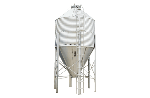
Vertical cylindrical silos are the most common structural type, consisting of a cylindrical shell and a conical bottom.
With a circular cross-section, this structure features uniform stress distribution and high material utilization. The bottom cone angle is determined according to the material’s angle of repose, generally ranging from 45° to 70°. A larger cone angle improves material fluidity but increases the overall height of the silo.
In the design of vertical cylindrical silos, the shell diameter is determined by volume and site conditions, with the height-to-diameter ratio normally controlled within 1:1 to 3:1. The cone hopper angle shall be greater than the friction angle between materials and the silo wall to ensure smooth gravity-driven material flow. The outlet size of the cone hopper shall take material particle size and discharging speed requirements into account. An undersized outlet easily causes blockage, while an oversized one may lead to material surging. This type of silo is highly suitable for storing free-flowing granular and powdery materials, such as plastic pellets, grain and cement.
Horizontal silos are another prevalent structural form, featuring a horizontally arranged axis with elliptical or dished heads at both ends.
They have a low center of gravity, excellent stability and a low installation height, facilitating feeding operations. However, horizontal silos occupy a larger floor area and deliver less smooth discharging compared with vertical silos, often requiring mechanical devices for complete emptying.
In horizontal silo design, screw conveyors or belt conveyors are generally installed at the bottom for forced discharging. For materials prone to caking, internal stirring devices can be equipped to prevent compaction. Special attention shall be paid to the strength calculation of end heads due to complex stress conditions in these areas. Horizontal silos are ideal for materials with poor fluidity and high caking tendency, or renovation projects with limited installation height.
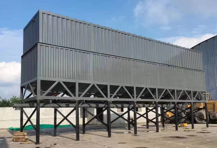
Square or rectangular silos are mostly applied in space-constrained scenarios or occasions requiring side-by-side arrangement.They feature flexible layout and high space utilization, allowing more silos to be arranged in limited space. Nevertheless, square silos suffer from stress concentration at corner positions, requiring reinforced design to guarantee structural strength. In addition, materials tend to accumulate at corners and form discharging dead zones, which must be addressed in design.For square silos, arc transitions are recommended at corners to reduce stress concentration and material retention. Stiffeners shall be arranged on side walls to prevent bulging and deformation, and eccentric discharge outlets are preferred to optimize material flow. Square silos are applicable to small-scale projects, multi-silo combined layout and space-limited renovation works.
Classification by Bottom Structure
Conical-bottom silos are the most widely adopted type, realizing gravity discharging without extra power.This bottom structure is simple with no moving parts and low maintenance workload. The selection of cone angle is critical in design. The cone angle must be greater than both the wall friction angle and internal friction angle of the material to achieve mass flow.Symmetrical cone hoppers with central discharge feature simple structure but easily cause funnel flow. Eccentric cone hoppers can optimize material flow and promote overall mass flow. The hopper wall shall be kept smooth; if necessary, stainless steel plates or polymer liners can be installed to reduce frictional resistance.
Flat-bottom silos have a horizontal base and cannot be completely emptied by gravity alone, requiring silo cleaning mechanisms or screw discharging devices.They are suitable for large-scale silos and materials with extremely poor fluidity, as the flat structure effectively reduces overall silo height. In design, screw conveyors or scraper conveyors are installed at the bottom for forced discharge. Corner areas between the flat base and side walls are prone to material accumulation, so cleaning devices are required for regular removal. For large flat-bottom silos, safety measures must be considered for manual internal maintenance and cleaning operations.
Fluidized-bottom silos are equipped with fluidization plates at the bottom of cone hoppers. Compressed air is injected to fluidize materials and improve their flow performance.This structure is highly suitable for poorly flowing powdery materials that are prone to bridging. In design, fluidization plates shall be made of air-permeable and anti-clogging materials, typically sintered metal plates and microporous plastic plates. Air volume and pressure shall be adjusted according to material properties; insufficient air fails to achieve fluidization, while excessive air may cause material spraying. Since fluidizing air carries dust emissions, a matched dust removal system is required for exhaust gas treatment.
Classification by Discharging Mode
Gravity-discharge silos rely entirely on material self-weight for discharging, with the simplest structure and the lowest operating cost. This mode applies to materials with good fluidity, sufficient cone angle and properly sized outlets. During design, sluice valves or rotary valves shall be installed at the outlet to regulate flow rate, and discharging speed shall be calculated to avoid material surging.
Mechanical-discharge silos are equipped with discharging equipment such as screw conveyors, belt conveyors and vibrating feeders. They are suitable for materials with poor fluidity or processes requiring precise discharge control. The design shall ensure that discharging capacity matches downstream equipment. For screw conveyors, wear resistance and torque load shall be considered, while vibrating feeders need vibration isolation measures to prevent vibration transmission to the silo body.
Pneumatic-discharge silos transport materials out by means of compressed air, mainly used for powdery materials especially in long-distance conveying scenarios. The design requires fluidized beds or air blowing devices. Conveying pipelines shall be optimized based on flow velocity, material concentration and pressure loss, with complete air supply and dust removal systems configured.
In addition to the above basic types, special-structure silos are developed to solve specific operational problems.Anti-bridging silos adopt customized structures on cone hoppers to eliminate material arching. Common solutions include installing vibratory activation cones to break arches by vibration, deploying air cannons to crush material bridges through instant compressed air injection, and mounting vibration motors on hopper walls to assist material flow.
Anti-segregation silos are designed to reduce segregation of mixed materials. Key measures include adopting multi-point feeding instead of single central feeding to avoid natural grading, installing internal flow guide cones or baffles to redistribute materials, and applying short-and-wide structural design to shorten material falling distance.
Key Design Parameters & Design Process
Silo design involves multiple critical parameters that require rigorous demonstration. Volume determines storage capacity, calculated based on material bulk density and filling coefficient. The height-to-diameter ratio affects flow pattern, structural stability and floor area, requiring comprehensive trade-offs. The cone angle, a core factor for smooth discharging, shall be 5° to 10° larger than the material’s angle of repose. The outlet size should be 3 to 5 times the maximum material particle size to prevent blockage. Shell thickness calculation takes static pressure, wind load, seismic action and wear allowance into consideration to ensure structural safety. Reasonably arranged stiffeners can enhance structural rigidity, reduce plate thickness and save material costs.
The conventional silo design process starts with material property testing, including particle size distribution, bulk density, angle of repose, internal friction angle, wall friction angle and compressibility. These parameters determine the material flow pattern (mass flow or funnel flow), followed by structural dimension confirmation of volume, height-to-diameter ratio, cone angle and outlet size. Next, structural strength calculation is conducted to define shell thickness, stiffener layout and support structure. Discharging devices are selected according to material characteristics and process requirements. Finally, auxiliary components such as level gauges, manholes, dust removal ports and maintenance platforms are arranged, along with safety design for explosion protection, static elimination and overpressure prevention.
In conclusion, silo design is a comprehensive technology integrating powder engineering, structural mechanics and process requirements. Only by fully mastering material properties and flow rules can designers develop high-quality silos with smooth discharging and stable operation, providing reliable solid material storage support for industrial production.